P R O L O G U E
Optop RRC: (mid October 2018)
I have updated (hardware, circuitry and software the of initial Optop build to Optop RCC (Remote Record Control). The RCC version has:
- Increased clearances to permit the playing of large rolls to completion. (Technically trivial, but it was the impetus for the rebuild.)
- Two serial streams one at 31,250 baud (MIDI) and the other at 38,400 baud (conventional duplex serial).
- Windows code for remote control of Optop RCC hardware with run (and record), stop, rewind and about functions.
- One less microcontroller. (Hardware interface logic implemented in main microcontroller.)
- Serial LCD display.
- Fully floating belt driven take-up roll.
Jase Haysom email contact:
It has recently been brought to our attention that a number of spurious web references to the invention of the player piano are lamentably widespread. In particular the page on the History of the Piano, at [URL], is full of the most glaring inaccuracies, which have been copied and re-broadcast by countless other parasitical websites. John McTammany is credited with the award of a patent for a piano player in 1881, when in truth his first patent was not awarded until 1883, and was not for a piano player in any case. One Edward Leveaux, an Englishman who invented an ingenious system of springs in order to store motive power, but who had nothing at all to do with player pianos, is described as patenting the Angelus player, some seventeen years before it was actually introduced, and the repetition of this nonsense throughout the internet has even resulted in a coffee mug being marketed with the spurious inventor and his equally spurious patent. William Fleming is noted as having been awarded a patent for an electric player piano in 1889, when in fact W.B. Flemming's patents date from 1897 and 1899. It does not take long for such errors to become accepted fact, simply because they can be read in print. The Pianola Institute Ltd www.pianola.org/history/history.cfm accessed 2017/02/03
It would indeed be a game person who would plunge into any debate on the origin of the pianola. However,the Pianola Institute (www.pianola.org/), with hard copy publications dating back to 1987, presents with some authenticity.
Sufficient for our purpose is the observation that the pianola, or a variation thereof, first emerged late in the nineteenth century. The traditional pianola with its multiplicity of vacuum technology items – pumps, motors, solenoids and other devices – is an example of design ingenuity and craftsmanship. Some time ago a couple of my acquaintance, inexplicably (to my mind) purchased a pianola; I was surprised and mildly interested. Now, excuse me for drifting into the extravagant style of 19th c. literature, but little did I realize at the time into what an absorbing and complex labyrinth my friends' innocent acquisition would lead me.
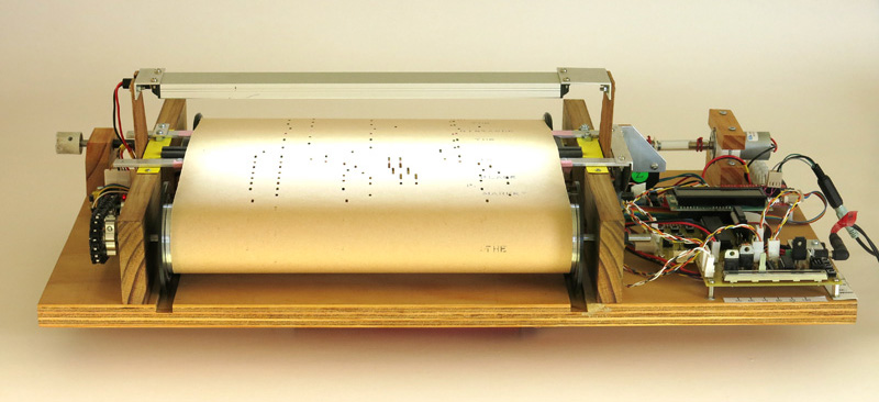
Aim: To produce an electronic pianola to play traditional pianola rolls in real time.

Method: In the optical pianola (Optop) the roll paper runs over an array of 88 optical sensors in much the same manner that it would run over the 88 note holes in the tracker bar of a conventional pianola. (Actually there are more than 88 holes in a tracker bar, but for simplicity we will restrict our discussion to the holes associated with the keyboard notes.) A strip light above the sensors provides illumination. The output of each optical sensor will present as 1 (light passes through a hole) or 0 (light is blocked by the paper). Thus the state of each note can be represented by a single digital bit, and the state of the pseudo keyboard can be represented by an 88 bit digital word.
To assist with processing, the 88 bit word is converted a sequence of 8 bit (1 byte) words. The conversion process is done by a multiplexer. At any particular instant the multiplexer selects 8 adjacent notes of the 88 available. The particular byte selected at the time is determined by the scan address. The multiplexer provides the selected byte to the microcontroller unit, MCU. The scan addresses are generated cyclically by the MCU to scan the entire keyboard eight notes at a time. Provided the scan rate is sufficiently high the MCU will be able to maintain an accurate instant by instant image of the keyboard.
The MCU can examine the keyboard image note by note to determine if a keydown event (a 0 becomes a 1) and keyup event (a 1 becomes a 0) has occurred for that note. From this information the MCU can generate a MIDI (Musical Instrument Digital Interface) stream. A MIDI stream is a series of digitally encoded commands that are sent from a controller (in this case the MCU) to a synthesizer (also known as a synth). The synthesizer responds to the commands to generate a particular note on a particular (synthesized) instrument. The notes are generated as analogue audio that provides input to a conventional sound system – This process is performed with sufficient rapidity to appear, well, that is, to sound, transparent.
Use: The download material on the Optop subdomain is available without restriction. (This is not the case for other ccmaps.au domains or subdomains.) However it would be welcomed if (in the case of Optop material) the name Optop, and the URL, optop.ccmaps.au, were preserved.
Optop contact: m.haysom@ccmaps.au
Jase.