G A L L E R Y

The image shows Version 1. However, the basic layout for the version 2 is similar. The strip LED light for illumination of the sensors is above the paper. The leads on the right are 12 volt supply in and line level audio out.
It is necessary to align the holes in the paper with the optical sensors and to maintain that alignment as the roll is played. The image above shows the mechanism to dynamically position the tracker bar. A pair of optical sensors at each side of the nomimal paper path provide feedback. This idea is nothing new, conventional pianolas use a vacuum system to achieve the same effect. Part of the array of 88 (plus) phototransistors can be seen between the two black HDPE rubbing strips.


The takeup roller in version 1 was fixed to the axle and the axle was driven via a chain sprocket. To avoid bearings and alignment difficulties a simpler arrangement was used for version 2. The roller free runs on the axle and is driven directly with a toothed belt. Alignment problems are avoided by the use of laser cut components. In the image above from left to right – a spacer (1 of 2) to locate the aluminium tube forming part of the takeup roll, a 3 mm pitch toothed belt sprocket that is also part of the takeup roll and a side support (1 of 2) for the LED strip light that provides the illumination for the optical sensors.
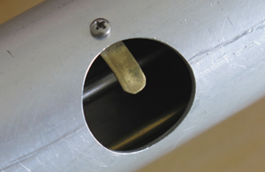
The image to the right shows detail of the takeup roll hook. The cut-out provides a lower profile when the roll is attached. The 6 mm fixed axle and one of the three assembly rods can be seen within the aluminium tube.

At the left end of the player is the spring-loaded retainer for the left end of the pianola roll.
In the rewind process the takeup motor runs in reverse, feeding the paper to pianola roll. The rewind motor drives the pianola roll to absorb the paper as it becomes available. The rewind motor current (and hence the torque) is limited by a series resistor. This arrangement avoids the need for a clutch. The image to the right shows part of the drive system. From right to to left: heavy wall rubber tubing (off screen to right is rewind motor), a constrictor knot [Ashley Book of Knots, Ashley C. W. #1249] locks the tubing down to the 6 mm shaft that carries the drive spigot. The end of the cageless needle bearing can be seen between the end of the tubing and support block.

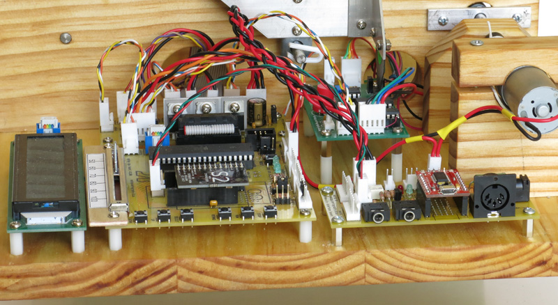
Most of the components in this image can be identified from the block diagram on the 'Design' page. In this instance the DreamBlaster S2 synthesizer is in place, the pinout on the CPU board will also carry the Adafruit FeatherWing MIDI Synth.
Use: The download material on the Optop subdomain is available without restriction. (This is not the case for other ccmaps.au domains or subdomains.) However it would be welcomed if (in the case of Optop material) the name Optop, and the URL, optop.ccmaps.au, were preserved.
Optop contact: m.haysom@ccmaps.au
Jase.